Medium Voltage (MV) Power Cables form the critical backbone of modern electrical distribution networks, operating between 1kV and 36kV (commonly up to 35kV). These specialized cables efficiently transmit substantial electrical power over medium distances, connecting substations to industrial facilities, commercial complexes, renewable energy plants, and urban infrastructure. Unlike low voltage cables, MV cables require sophisticated insulation systems and specialized construction to manage higher electrical stresses and ensure long-term reliability.
Medium Voltage Cable Classifications
1. By Voltage Rating (IEC System)
MV-A: 3.6/6kV (3.6kV to ground, 6kV phase-to-phase)
MV-B: 6/10kV, 8.7/15kV
MV-C: 12/20kV, 18/30kV
MV-D: 21/35kV, 26/45kV
2. By Insulation System
Paper-Insulated Lead-Covered (PILC):
Construction: Oil-impregnated paper insulation with lead alloy sheath
Advantages: Proven reliability, excellent moisture barrier
Limitations: Heavy, difficult to terminate, environmental concerns
Status: Legacy technology, being phased out in most regions
Cross-Linked Polyethylene (XLPE): Modern Standard
Advantages: Higher temperature rating (90°C normal), excellent moisture resistance, lighter weight, easier installation
Types: TR-XLPE (Tree Retardant), HFDA (High Frequency Dielectric Loss) grades
Applications: 95%+ of new installations globally
Ethylene Propylene Rubber (EPR/HEPR):
Advantages: Superior flexibility, excellent thermal stability, resistant to partial discharge
Applications: Mining, ships, frequent bending applications, harsh environments
3. By Conductor Design
Solid Conductor: Single solid wire (typically for smaller sizes)
Stranded Conductor: Multiple wires bundled together
Segmental/Sector Conductor: Compacted segments for reduced diameter
Milliken Conductor: Multiple insulated sub-conductors for very large cables
4. By Shielding System
Conductor Shield: Semi-conductive layer extruded over conductor
Insulation Shield: Semi-conductive layer extruded over insulation
Metallic Shield: Copper tape or wires for fault current path
Jacket/Sheath: Outer protective layer
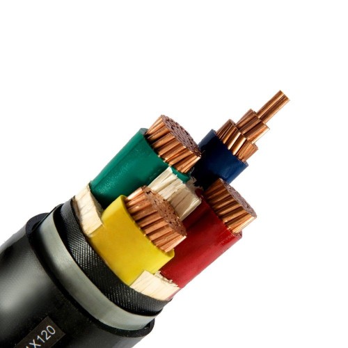
5. By Construction Type
Uni-Polar: Single conductor with full shielding
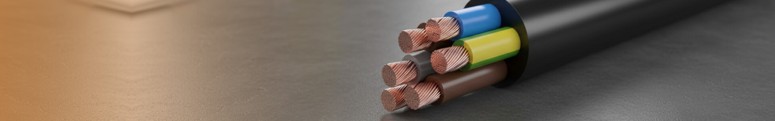
Multi-Core (3-Core): Three conductors in triangular or flat formation
Armored Types:
SWA: Steel Wire Armored
AWA: Aluminum Wire Armored
CSA: Corrugated Steel Armored
Specialized Types:
Submarine Cables: Water-blocked, reinforced
Fire-Resistant Cables: Maintain circuit integrity during fire
HVDC-Light: For renewable energy integration
Manufacturing Standards & Compliance
Primary International Standards
IEC 60502-2: Power cables with extruded insulation for rated voltages from 6kV to 30kV - Global Benchmark
IEC 60840: Power cables with extruded insulation for rated voltages above 30kV up to 150kV
IEC 60229: Tests on cable oversheaths which have a special protective function
IEC 60287: Calculation of current rating
Regional Standards
North America: AEIC CS5-94/6/7, IEEE 404, UL 1072, NEC Article 310
Europe: EN 50393-50667, HD 620, BS 6622/7835
UK: BS 6622 (XLPE), BS 7835 (armored XLPE)
Australia/New Zealand: AS/NZS 1429.1, AS/NZS 4961
Middle East: SASO 2770 (Saudi Arabia)
Asia: IS 7098 (India), GB/T 12706 (China), JIS C 3606 (Japan)
Detailed Technical Specifications
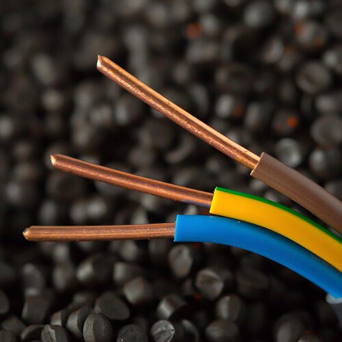
1. Conductor
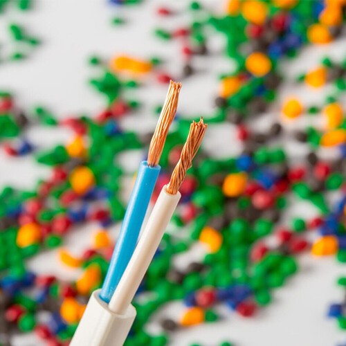
Material: Electrolytic copper (≥99.9%) or EC-grade aluminum
Classes: Class 2 (stranded) standard, Class 5 for flexibility
Shapes: Round, segmental, Milliken for large cross-sections (240mm² to 2000mm²)
Conductor Screen: Extruded semi-conductive layer (graphite-based XLPE)
2. Insulation System (XLPE)
Thickness: Based on voltage rating per IEC 60502-2 tables
Examples: 2.5mm (for 6/6kV), 4.5mm (for 12/20kV), 10.5mm (for 18/30kV)
Tree-Retardant: Special additives to prevent water treeing
3. Insulation Screen
Extruded semi-conductive layer
Bondable or strippable types available
4. Metallic Shield
Copper Tape: 0.1-0.15mm thickness, longitudinally applied
Copper Wires: Concentric wires (16-50mm² cross-section)
Function: Earth continuity, fault current capacity
5. Bedding/Filler
PVC or PP tape
Water-blocking tapes/swelling powders for underground cables
6. Armoring (Optional)
Galvanized Steel Wires: Round or flat
Aluminum Wires: Non-magnetic, lighter alternative
Corrugated Steel Tape: Moisture barrier + mechanical protection
7. Outer Sheath
Materials: PVC (ST1/ST2), PE (ST7), LSZH
Thickness: 2.0-4.5mm based on cable diameter
Colors: Standard black, red for fire-resistant, other colors available
Key Performance Parameters:
|
Specification
|
Typical Values
|
Test Standard
|
|
Voltage rating
|
6.6/11kV, 12/20kV, 18/30kV
|
IEC60502-2
|
|
Max operating temperature
|
90°C (XLPE), 85°C (EPR)
|
IEC60502-2
|
|
Short Circuit temperature
|
250°C (XLPE), 220°C (EPR)
|
IEC60502-2
|
|
Partial Discharge
|
≤5pC at 1.5U₀
|
IEC60885-3
|
|
Dielectric Loss (tan δ)
|
≤0.001 at 90°C
|
IEC60840
|
|
Bending Radius (Fixed)
|
12-20× overall diameter
|
IEC60502-2
|
|
Minimum installation temp
|
-20°C (PVC), -40°C (PE)
|
Manufacturer spec
|
|
Fault current capacity
|
1s to 3s rating (kA)
|
IEC60949
|
Critical Installation Parameters
Minimum Bending Radius: 12-20× cable diameter (permanent), 6-8× (during installation)
Pulling Tension: Max 50-70% of conductor yield strength
Termination Requirements: Stress control cones, sealing ends, proper glanding
Joining Methods: Heat-shrink, cold-shrink, premolded joints
Testing Protocol:
Insulation Resistance (IR) test: ≥1000 MΩ·km
High Voltage DC test: 2-4× U₀ for 15 minutes
Partial Discharge test: <5pC at 1.5U₀
Tan δ measurement for cable diagnostics
Common Installation Mistakes to Avoid
Exceeding bending radius during pulling
Inadequate trench preparation (sharp stones, thermal backfill)
Improper gland selection and installation
Incorrect phase identification
Insufficient separation from other cables/services
Poor water sealing at terminations
Medium voltage power cables represent sophisticated engineering systems where material science, electrical design, and mechanical protection converge. The evolution from PILC to modern XLPE/EPR cables has dramatically improved reliability, safety, and installation efficiency. When specifying MV cables, professionals must consider not just initial cost but total lifecycle value—factoring in installation complexity, maintenance requirements, and expected service life (typically 30-40 years for properly installed systems).
As global energy demands grow and grids modernize, MV cables will continue evolving with smarter monitoring capabilities, higher efficiency designs, and greater environmental sustainability. Understanding these classifications, standards, and specifications empowers engineers to make informed decisions that ensure safe, reliable power distribution for decades to come.


 482
482


 Admin
Admin
 Jan 28 2026
Read More
Jan 28 2026
Read More